The BVM Electra jet "kit" lead the way. Its size and performance have
revolutionized the state-of-the-art for an all electric jet model.
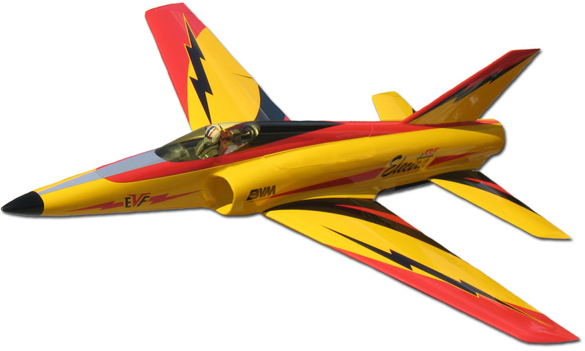
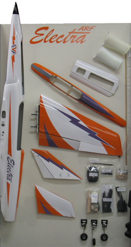
The Electra jet "ARF" has all the same performance and mechanical features of
the kit version, but with 90% of the labor to build and finish accomplished for
you. Its all composite, painted-in-the-mold airframe is strong and light. With
the BVM Electric VioFan, it is flight worthy at speeds up to 200mph, but
stable slow flight and easy landings are where the Electra Jet really shines.
Let’s take a closer look at why you may consider owning this very special ARF
jet.
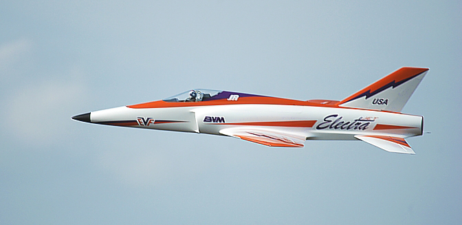
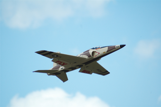
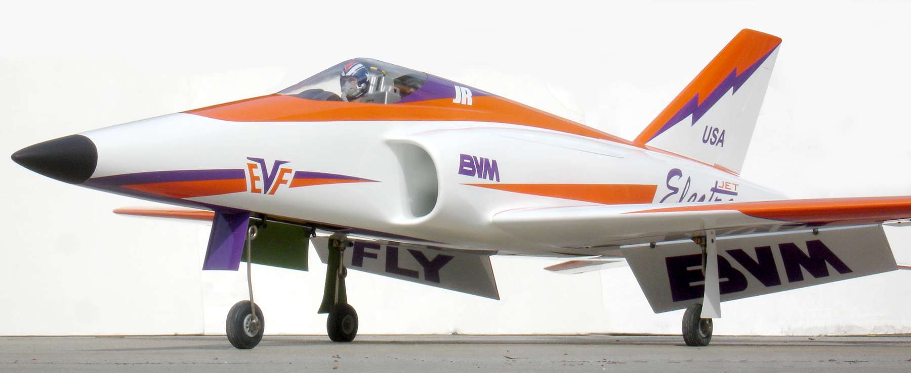
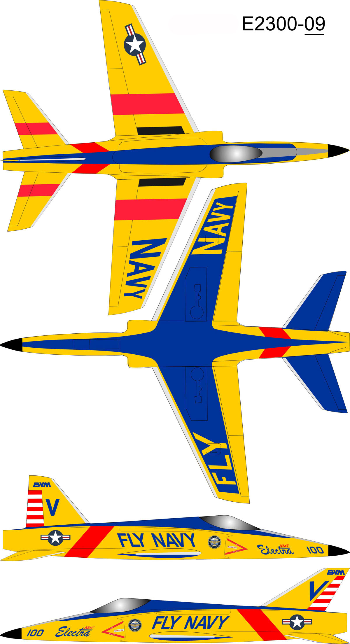
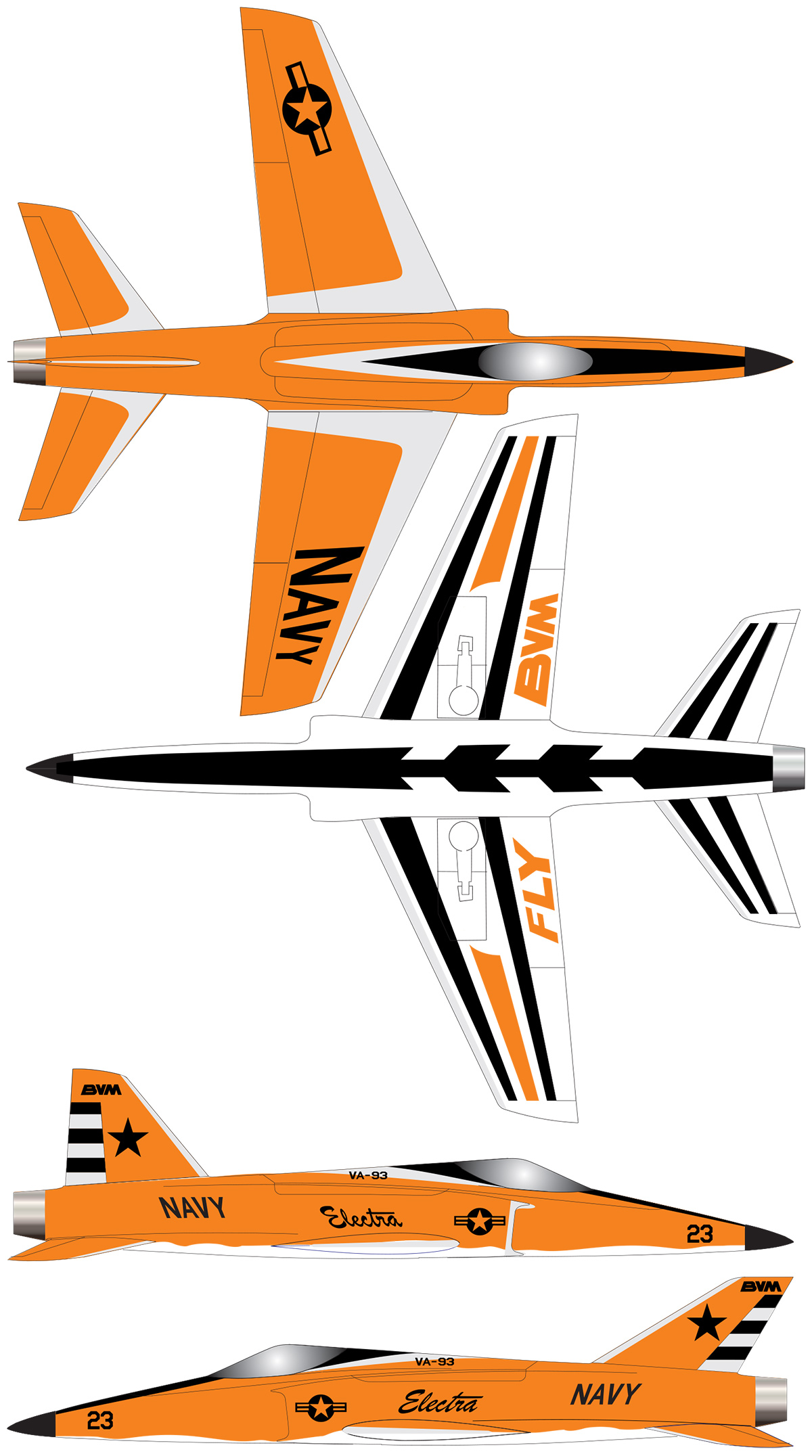
The Flying
Slow •
Fast • Aerobatic
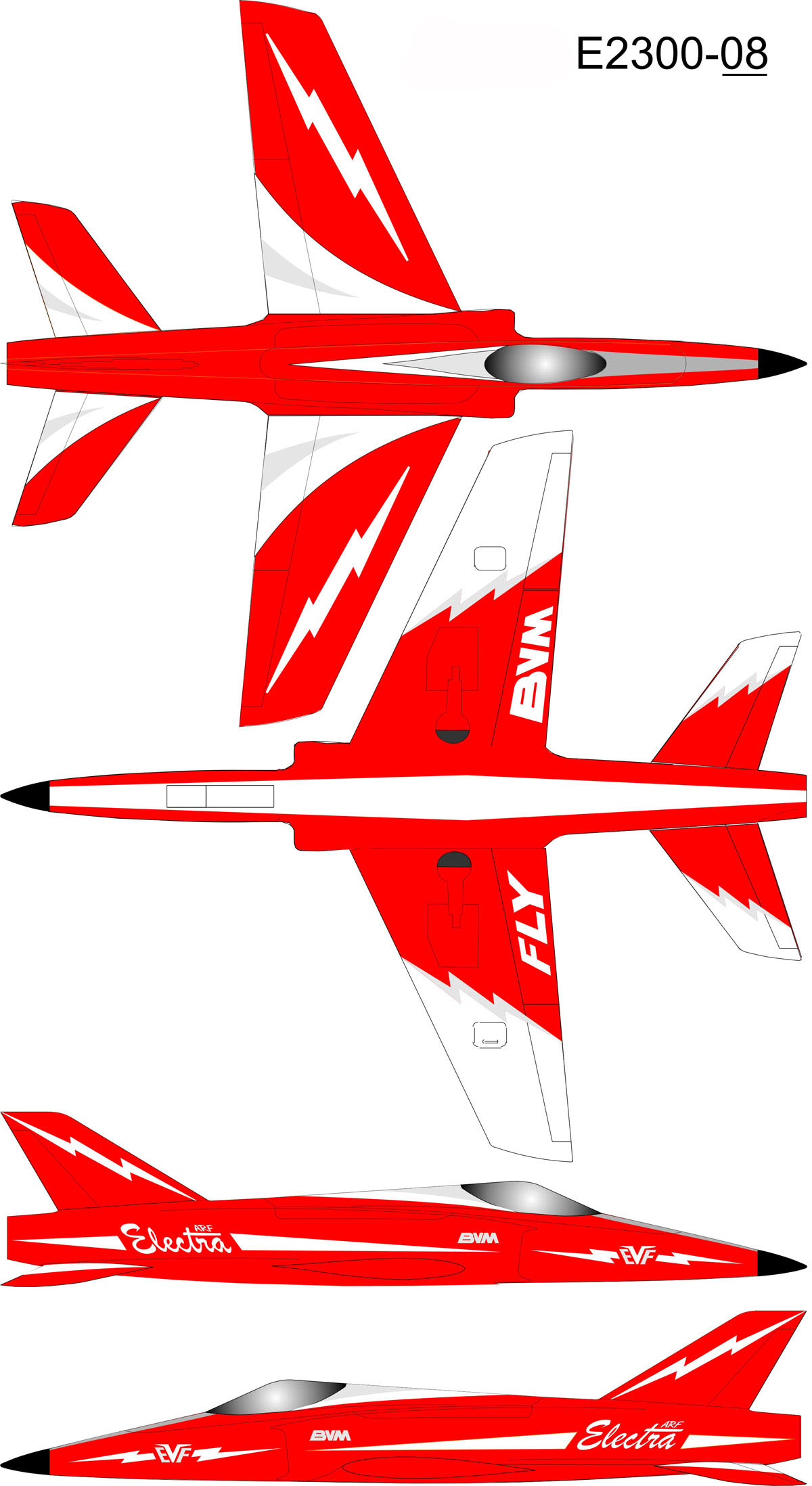
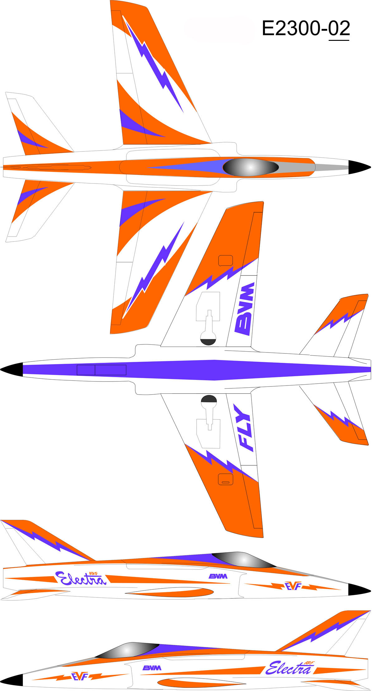
The "CLASSIC" in white, orange, and purple.
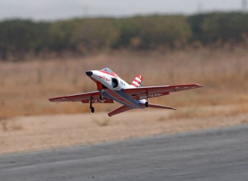
BVM has always believed
in showing you first hand just how our products perform. Many BVM
Reps are flying Electra's at model events, so you may get to see one
soon. Then, you be the judge. You can also see
video on our website.
The airframe structure is a combined effort of BVM’s USA based
tooling and internal parts manufacturing, and our Thailand
counterpart’s laminating, painting, and finishing capabilities.
Every Electra ARF is quality controlled at our Florida facility
and then repackaged with BVM hardware, plans, and absolutely
complete instructions.
A crystal clear canopy, molded cockpit deck and instrument panel
are standard.
Some assembly of internal parts required.
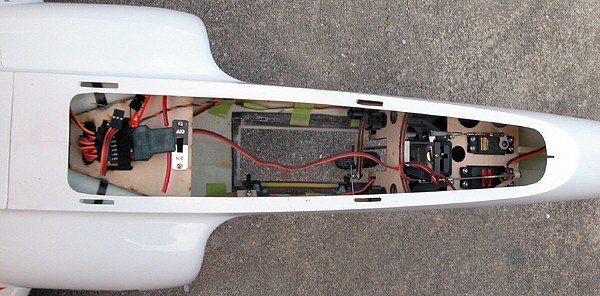
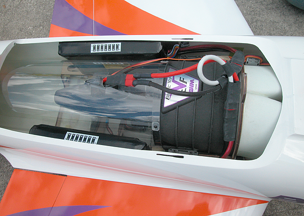
Access is Important
Even though the power and guidance components are minimum in this "all
electric" jet, easy access to them is a convenient feature of your Electra.
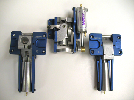
Strong & Light Undercarriage
Hundreds of landings without a glitch
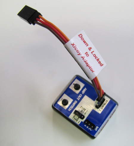
Down & Locked Gear Driver with Xicoy Adaptor
Air Blue Retracts
E-Blue Retracts
Because some modelers prefer air operated landing gear, BVM
developed the "Air/Blue" retract units specifically to fit into flex
mounts in the Electra.
The "air" installation package contains all of the pneumatic valve,
"T" fittings, tubing, and storage tank required.
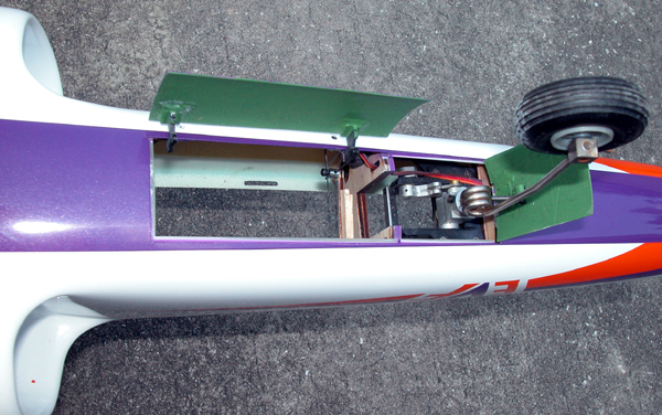
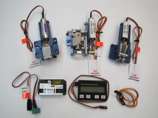
An important part of an all electric jet is the landing gear system.
Shown here is the latest generation of the electric landing gear system and
the BVM adapted "Xicoy Controller". BVM created an easy to follow manual for
the installation and programming.
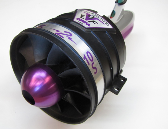
Professionally Designed - Professionally Manufactured
The EVF (Electric VioFan) comes to you completely assembled and
factory test run.
Available for 10 to 12 cell operation.
2 Year Warranty
It’s just right for a one person operation.
US Pat# 8,310,117 B2
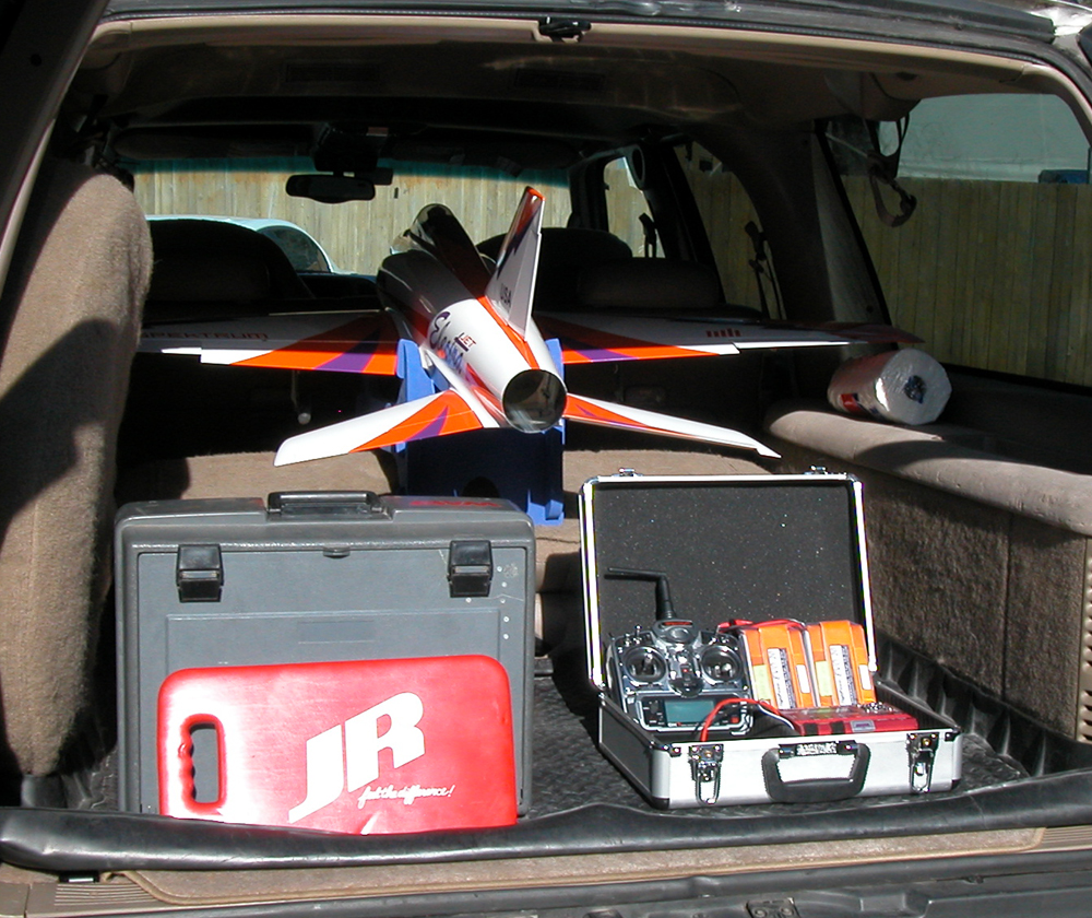
The Convenience
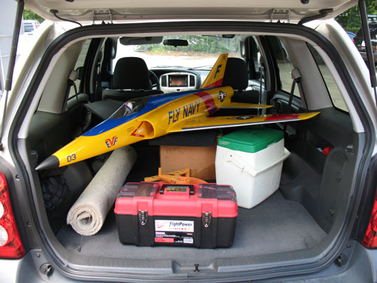
The Electra Jet ARF will
fit into most SUV’s with the wings attached. Of course, the plug-in
wings and stabs are easily removed for more compact transport and
storage.
And, if air travel allows you to enjoy
attending certain important events, the Electra ARF can be safely
transported in the BVM Jet Case.
The Benefits -
of electric propulsion
l
Zero throttle lag and zero
residual thrust; makes landing an electric jet easier than a
turbine jet, especially in a crosswind.
l No turbine waiver needed.
l Minimum support equipment
necessary - bring spare batteries and a charger for more
flights.
l No vibration to wear out components.
l No liquid fuel to saturate the
inside of your model.
l Low heat environment.
l Electric Reliability.
l 150+mph performance.
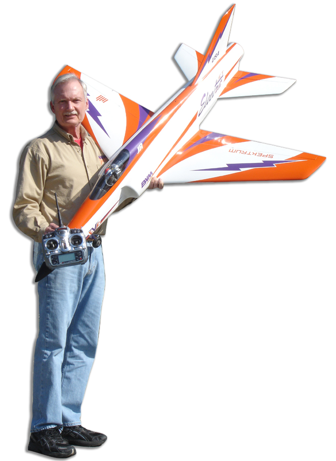
The Electra Jet is big (60" wingspan) for an
electric powered sport jet, but still compact enough to fit into many
midsize SUV's like Bob Fiorenzi's Mazda Tribute. Shown here
with the wing and tail covers removed, it rests on a foam padded box
and there is still space available for spare batteries, chargers,
and a cooler.
Electra Jet
ARF
Airframe Directive (A.D.)
And other helpful notes
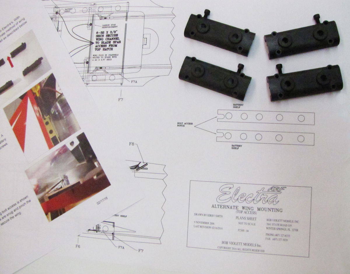
Electra ARF Instructions Updated to show wing removal from fuselage top access.
(02/19/2016)
Ask for BVM # E2300-64 Price
$47.95
Qty. 4 per package
This simple machine made maple block assembly makes the
rudder servo installation much easier. It is available at no charge to
Electra (Kit or ARF) and Sabre (AFS or ARF) owners with your next purchase from
BVM.
Kits shipped after September 2009 have these parts and
instruction updates included.
Note: All E Jets are built
light weight. Give due consideration when handling each F/G component.
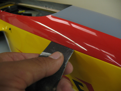
Canopy and Engine Hatches Lapping Addendum
(06/10/2009)
As a final procedure for fitting the canopy and engine hatches,
use a piece of #220 grit sandpaper (grit up) slid between the fuse
flange and hatch and "lap-in" any tight spots for a relaxed fit of
the hatch to the fuse.
Retract Pushrod Addendum
(06/08/2009)
From: Bob Belluomini
To: Bob
Sent: Tuesday, June 02, 2009 12:48 PM
Subject: Electra Retract Pushrod Mod
Hi Bob,
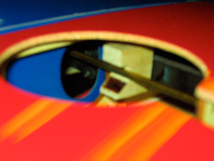
I incorporated a small mod that limits how far the retract
pushrod bends. I reduced the overall throw at the servo so as to reduce the
twisting action that occurs at the servo mount and former. With the gear in the
down position I cut a j shaped notch in two of the blocks that are used to mount
the servos, one for each side. The notch is cut just deep enough so the pushrod
rests against it with the block mounted on the back of the front blade spar
about 3/16" out from root of the wing. The blocks are mounted at 180 to each
other to allow the pushrod to go through it stroke correctly.
If you depress the over center link on the retract by hand
you will see the motion is transferred to the other retract unit making it
impossible for either retract to unlock.
Thanks,
Bob Belluomini
F8 Installation Addendum
(06/08/2009)
The canopy frame is of very lightweight
fiberglass structure, support the model on soft foam rubber for the installation
of F8 on page 71 of the manual.
EVF Tailpipe
(12/09/2008)
The original BVM Electra jets have hundreds of
flights on the original tailpipes taped together per the instructions. We have
heard of a few in-the field that have had the taped seams open up. This will
cause a very noticeable loss of thrust. If you experience noticeable loss of
thrust, land as soon as practical. Check the tailpipe seam and batteries of
course.
To repair the tailpipe, remove it, strip away
the tape and clean the tape residue off with 3M Adhesive Cleaner #08984
(available at auto paint supply stores). Then rebuild the tailpipe as per the
instructions.
Flap Setting Addendum (10/02/2008)
The landing flap position that we recommend
in the manual may be a bit too much for some landing techniques. It works
if you add a bit of power just prior to touch down. For a total power-off
flare out, a setting of about 10°
less will afford smoother landings. Try it and let us know what you think.
Main Gear
Flex Mount Stiffener Addendum (09/30/2008)
Main Gear
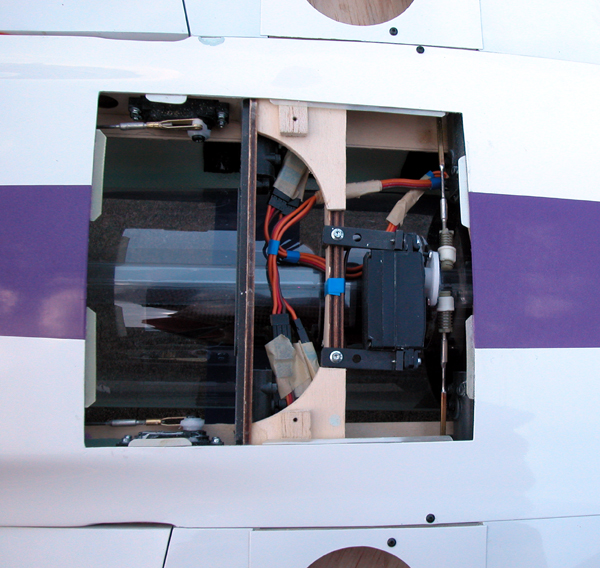
Retract Servo Installation Addendum (09/11/2008)
The following instructions and photos clarify
what has been published in the assembly manual and plans. The
location of the main gear servo mounting is important for the proper
function of the retracting mechanism.
It is important that the aft end of the
inlet ducts is centered in the fuselage. The Saddle CellsTM require equal
space on each side of the thrust tube.
Contact Us
All graphics, photos, and text
Copyright 2016 BVM, Inc. Use of graphics or photos without written permission from
BVM is
strictly prohibited.