F-100 D Hot Shots |
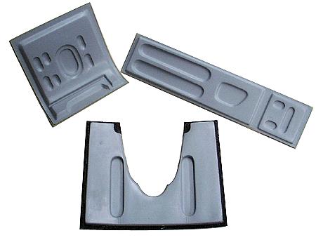
Jet Foam Cradle |
Fuel System Flush Mount
Fitting |
Kit Addendums | Major Kit Components | Structure
Highlights |
F-100 in a Jet Case | Color Schemes | Super
Scale Features| F-100 Landing Gear |
Recent flights & video | Wing Fences | Refueling Probe &
Pitot Tube | Cockpit
Gearing up your F-100 | Recent Updates | F-100 Sport Flying | Flying the REAL F-100F | Customers with
their F-100's
Specifications
LENGTH: 83.5"
WING SPAN: 69"
WING AREA: 1200 + sq. in.
WEIGHT: 29-31 lbs
SCALE: 1:6.75 or slightly larger than 1/7th scale
The model is sized to operate with a JetCat
P-120 or 160, AMT Pegasus, or RAM 1000 engine and weigh about 27 to 29 pounds.
Wing area is over 1,200 square inches.
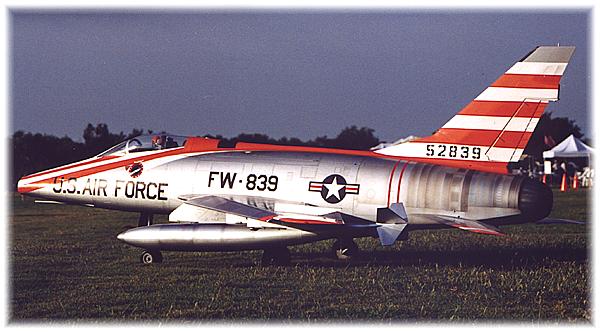
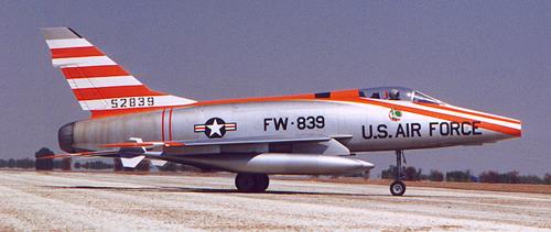
We reverse engineered a real bone yard F-100D to produce
an exact scale outline model - something that any scale jet enthusiast would be
proud to own.
The
F-100D is very easy to assemble and service and despite its size, it completely
disassembles to fit into the BVM JET-CASE, making it very easy to transport.
|
See how the first flights went on the F-100.
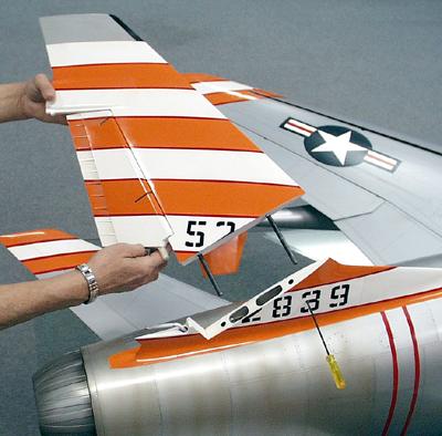
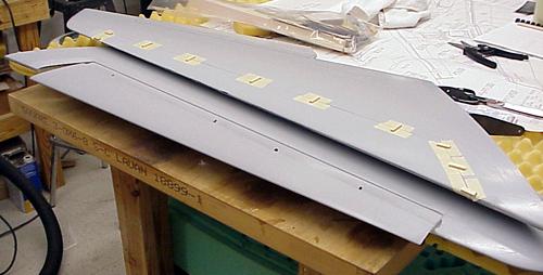
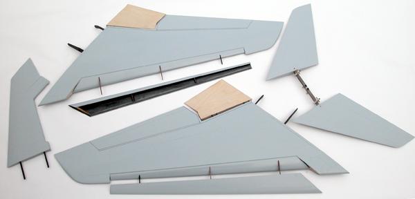
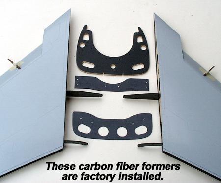
Major Kit
Components
All components are composite except the
flaps. Flaps are built at the factory with hinges installed. Leading edge slat
tracks are factory installed for easy finishing. Stabs are checked for perfect
alignment on a surface plate and shipped bolted together as shown
above.
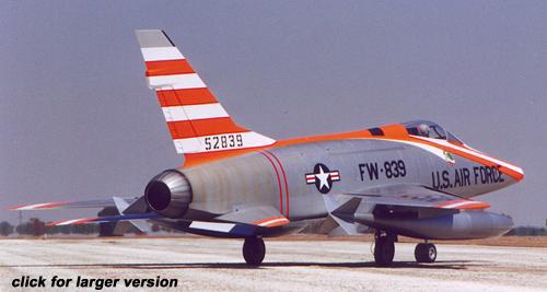
F-100 Super Sabre
Scale Outline
Accuracy is important |
The real
test for "accuracy of outline" is placing your model in front of Top Gun judges
- they rarely miss a detail.
Most of
these judges have years of experience at Top Gun making them the most critical
and yet consistent in the business. That is why we are very pleased with their
comparison of the BVM F-100D to the 3-view drawings as printed in the War Paint
Series #4 book on the North American Super Sabre.
The model received 29.25 out of a possible 30.00 points for accuracy
of outline. This means that the basics are there for a serious scale
enthusiast. An owner of a BVM F-100 can feel confident that his efforts to
finish and detail his jet will not be in vein when it's time to put it in front
of the judges.
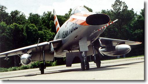
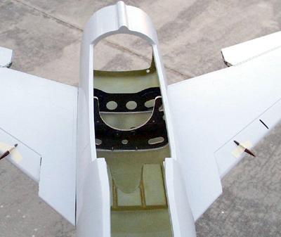
The Inlet opening
The relatively small opening and sharp lip of the F-100 inlet
prohibited its accurate scale modeling prior to turbine power. This and other
details like the 20mm gun recesses are faithfully reproduced in the BVM
moldings. Note also in this low angle view how prominent the leading edge slats
are in the extended position.
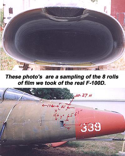
The inlet of the F-100 must be right or the whole front of the
fuselage suffers. Since we had access to a real F-100, we actually put a
plywood plate, covered with poster board, over the front of the aircraft's
inlet and traced it. We then used our "Faro" digitizing arm to record the X-Y
components into our AutoCAD system and accurately reproduce it to the 1:6.857
scale of the BVM model.
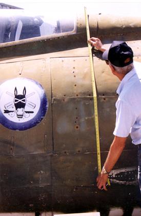
The Boneyard
F-100
Serious scale modelers would give anything to have access to the
real thing - especially one that was disassembled. We were lucky to find an
F-100D in just this condition in Florida, and we visited the site 4 times with
camera's, measuring equipment, a ladder and drawing supplies to be able to
reverse engineer the airframe.
This investment of time at the onset of the project pays off in the
long run because the investment in the production tooling is secure.
Customer confidence and satisfaction that he
has an accurate model is the ultimate reward.
F-100 Flight
Scores
The highest in Designer
Scale
Jeff Foley (1st with an BF-109E) and Nick Ziroli Jr (2nd with an
Avenger) had the edge in static scoring and they deserved it. The time and
experience these guys put into their models must be matched if you want to beat
them because they both fly very well too.
The top 3 places in this tough category were separated by less than
1/4 of a point as shown by their scores 1st - 191.541, 2nd - 191.375, 3rd -
191.333.
I was pleased that the
F-100 could score so well in the flight category - it has the smoothness and
performance to be a winner, especially in crosswind conditions. |
F-100 Super Sabre
Super Scale
Feature
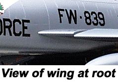
"Thin Flying Surfaces" |
 The F-100 was the first
operational jet fighter for the U.S. Air Force that was designed to operate
supersonic. Experienced gained by the early X plane development programs
allowed North American to design and build very thin, low drag flying surfaces
that could also withstand the stresses of MACH 1 plus flight. The F-100 was the first
operational jet fighter for the U.S. Air Force that was designed to operate
supersonic. Experienced gained by the early X plane development programs
allowed North American to design and build very thin, low drag flying surfaces
that could also withstand the stresses of MACH 1 plus flight.
We had
access to a bone yard F-100 that we reverse engineered to design the BVM model.
When we first measured the thickness (or better, the thinness) of the flying
surfaces, we knew we had a challenge.
We also knew that to build
them "fat" would certainly be easier, but not scale or authentic looking. Our
philosophy was; why go to all the trouble and expense to build the tooling and
then have to look at a fat wing, stab and fin with
disappointment.
As we mentioned earlier,
the scale NACA 64A007 airfoil was used for the wing along with operational
leading edge slats to make the thin wing act like it is fat for take-off
and landing.
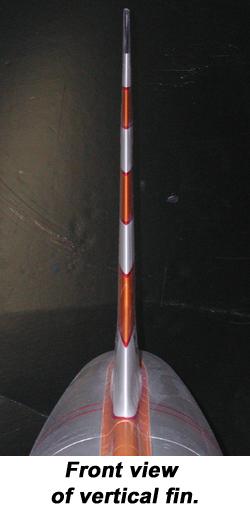
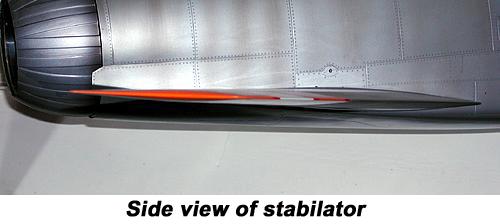
The fin, fin base on the fuse and the stabilators offered
some special challenges to duplicate those sharp leading and trailing
 edges and
the overall thinness ratio of the surfaces. edges and
the overall thinness ratio of the surfaces.
Thanks to super materials
like Carbon Fiber and Titanium we were able to meet the engineering challenges
and produce light weight, truely scale, supersonic looking flying surfaces that
have demonstrated their air worthiness many times at 200+ m.p.h.
speeds.
|
"Thin is in"
on a
real jet fighter |
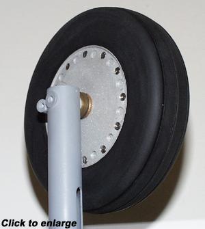
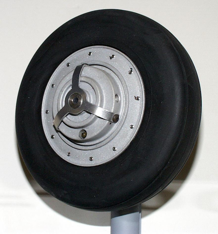
F-100 D Fine Feature
Super Scale Undercarriage |
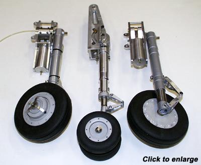 |
Every
truly scale jet needs a scale landing gear made exclusively for it or it just
won't look convincing or function properly. That's what we have learned over
the years at BVM.
The
capability to design and manufacture such items can only come from a mature
company that has acquired the skills and equipment to do so. This beautiful and
functional landing gear system for our F-100D reflects that capability.
Flight testing has allowed us to fine tune the
design and present to the customer a system that he will be proud to
own.
Since we all occasionally
"prang one in", parts and service are extremely important. Again, it takes a
mature company to be able to back up the product for many years to
come.
|
|
 |
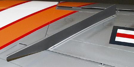
F-100 Wing Fences
optional
parts
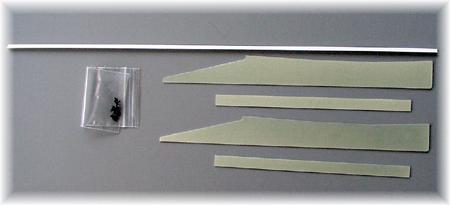 |
 Most
F-100D's had wing fences applied to the upper outboard sections. The exact
location is determined by the molded dots in the top wing skin. Most
F-100D's had wing fences applied to the upper outboard sections. The exact
location is determined by the molded dots in the top wing skin.
BVM has machined the fences and a base strip
from .030" poly ply and provided a plan and brief instruction sheet to make the
installation easy. The fence base strip is attached with 4 panel screws each
allowing removal for Jet Case transport.
|
 |
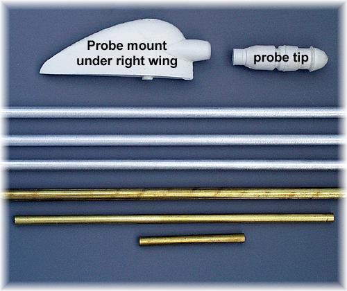
F-100 Refueling Probe & Pitot
Tube
|
F-100's had both straight and bent refueling
probe's. To replicate the bent version, apply an extension spring (tight
winding) to the O.D. of the tube. Use the drawing (included) to locate the
bends.
|
 |
|
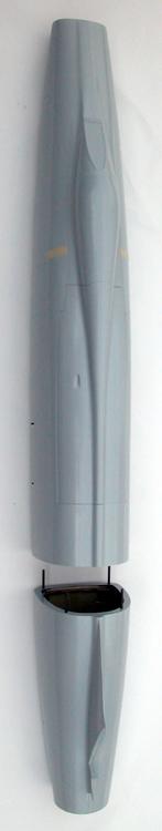
F-100 in a Jet Case |
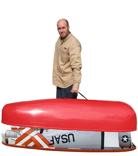 |
It took
some planning in the early stages of developing the F-100 to allow it to be
transported in our UPS and Airline acceptable "Jet Case". Notice that the aft
fuse section fits over the nose of the forward section and that the wing flaps
are removed. Even the aft wing spars were shaped to conform to the molded
fiberglass container.
Careful
wrapping of the parts in a high density foam allows all but the hot section
tailpipe to be safely air freighted to your destination. A separate cardboard
tube can be used to send the tailpipe and external stores.
Transportability is another great reason to
own a BVM F-100D. |
PRICING
| JET KIT |
| 9700 |
F-100 D |
$4,925.00 |
| |
includes -
airframe (all composite) with hardware, cockpit deck,
plans & instructions. |
|
| |
|
|
|
LANDING GEAR SYSTEM |
|
| 9710 |
Landing Gear System
(complete) |
$2,397.75 |
| |
includes -
retracts, air install package w/door cylinders, struts,
wheels, brakes, and Smooth Stop brake valve. |
|
| |
|
|
|
TURBINE INSTALLATION KITS |
|
|
All turbine installation kits include BVM Bypass system,
S.S. tailpipe (double wall), S.S. augmenter, and
hardware. |
|
| |
JetCat P-180 RX
|
$685.00 |
| |
Jet Central Cheetah |
$625.00 |
| |
Jet Central Rhino |
$685.00 |
| |
KingTech K-180G |
$685.00 |
| |
|
| FUEL
CELLS |
|
| 6105 |
Kevlar Kerosene Fuel
Cells |
$450.00 |
| |
|
|
| |
| Options:
|
| 1955 |
F-100 Aft Hot Section paint kit |
$72.50 |
| 9720 |
Wing Tanks - pair |
$425.00 |
| 9725 |
Pylon kit (complete set of 6) |
$525.00 |
| 9727 |
Inboard pylons (2) |
$185.00 |
| 9728 |
Midwing pylons (2) |
$175.00 |
| 9729 |
Outboard pylons (2) |
$185.00 |
| K9700-50 |
Cockpit detail kit |
$334.95 |
| 9565 |
Aeropoxy glue kit |
$87.95 |
| |
Includes - glue gun, 2
glue cartridges, 2 long nozzles and 2 short nozzles |
|
| 9735 |
Wing Fences - pr |
$27.95 |
| 9737 |
Molded Refueling Probe and Pitot
Tube |
$62.00 |
| 650 |
Jet Case (f/g molded) |
$629.00 |
| |
|
|
|
PRICES SUBJECT TO CHANGE WITHOUT NOTICE AND APPLY TO
SALES WITHIN USA ONLY.
Bob Violett Models Inc. 3481
State Road 419 Winter Springs, Florida 32708
USA tel 407-327-6333 fax 407-327-5020
www.bvmjets.com |
F-100
Airframe Directive (A.D.)
And other helpful notes
Large Fuel Cell Transfer
Tubes
Replace Brass with Stainless Steel
(4/20/06)
 There has been one case where the brass
tube that transfers fuel through a hole in the fuel cell baffle experienced
a razor saw-like cut. The engine flamed out because the remaining fuel below
the tube was unusable. There has been one case where the brass
tube that transfers fuel through a hole in the fuel cell baffle experienced
a razor saw-like cut. The engine flamed out because the remaining fuel below
the tube was unusable.
The most likely cause of the brass tubing
failure was many miles of trailer transport of the model with the fuel cells
empty.
The Fix
BVM
now supplies Stainless Steel tubes with the large baffled fuel cells i.e., KingCat,
F-100, F-4, Rafale, F-86 (80"). Retrofit parts are available. Ask for part
#PS-TU-0003 (quantity 2) price $5.00 for the pair.
To
be honest, we don't know how many travel miles the brass tubes will withstand.
It could vary quite a bit. BVM is converting our factory demo models as time
allows. Our prototype F-100D is 6 years old, has at least 300 flights and more
trailer miles than we can count. We inspected the brass tubes and found minimum
wear. We changed them to the Stainless Steel variety anyway.
Wing Pylon Mounting
- Locate drill locations per plans.
- Drill pilot holes with 1/8” bit. be sure to
align drill vertically with respect to ground stance of model. (not surface of
wing skin).
- Re-drill with 3/16 bit, then with 13/64” bit.
(hole size is critical for proper installation of brass insert.)
- Install brass insert onto 4-40 socket head bolt.
Slowly thread insert into hole. Maintain vertical alignment to avoid braking
maple block loose in wing.
- Remove bolt from insert, if insert does not
release, place a drop of water into hole to swell maple block around insert.
Wait 10 minutes, then try to remove bolt again. If needed, a drop of ZAP can be
used to hold insert in position in block.
F-100D & F
Stab Servo Arms
The details and instructions on the top
view of the fuse plans show and emphasis that the stab pushrod clevises are
connected to the 2nd hole from the center of the JR 215 heavy duty arms.
THIS IS CORRECT.
The photo on page 54 of the "D" model and page 63 of the "F" model
should be replaced with this image.

Trailer Transporting
the "Heavy
Jets"
It is convenient to transport the F-100
and F-4 gear down and strapped to shelves in the trailer. However, we are
seeing some wear and tear on the wing mounting formers in the fuselage. The
#10-32 bolts are working loose and even stripping the threads on the carbon
fiber threaded discs. Of course, occasional stiff landings further aggrivate
this problem.
Supporting the model on foam rubber on the trailer shelf should
greatly alleviate the problem.
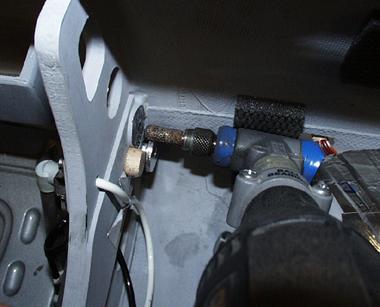
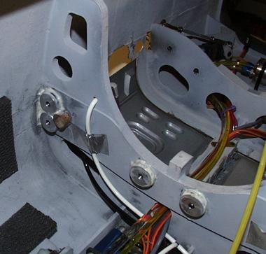
To fix a stripped out receptacle we made some aluminum
threaded inserts. See photo's for how to attach.
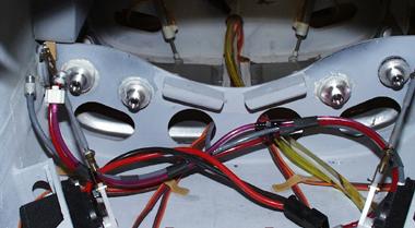
To add the threaded
aluminum inserts (BVM #2880) to the rear wing mounting formers, first scuff
with #80 grit, tack with slow CA, then surround with Aeropoxy.
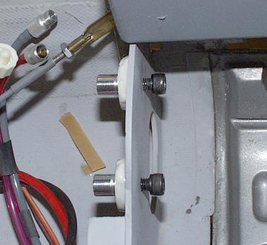
Use a 90° Dremel
tool and a Perma-Grit RF-5C to open holes in the forward wing mount former to
accept the aluminum insert shaft. Accomplish one at a time, checking alignment
with wing attached.
You should also
periodically check the 4-40 bolts that attach the main gear to the carbon fiber
wing spars.
F-100 Rudder Trim
It is hard to observe at a glance
because of the scale bulge in the fin at the top of the rudder and because the
rudder is thicker than the fuse fairing at the bottom. Take a close look before
take-off.
F-100 Tailpipe Cooling Shroud
A few of the very early kits may need
to have this part updated. The correct exit diameter at the rear of the outer
pipe is 3-3/4". If yours is less, return it for a no charge upgrade. The
upgrade deletes the need to wrap the outside of the pipe with the heat blanket.
The new system runs cooler.
F-100 Flap Geometry Improved
A second look at the flap linkage
produced better results. It uses all of the same parts but realizes a better
advantage in both the up and full down position.
As with any control surface linkage system, be
sure that the surface will travel freely beyond the prescribed limits so that
the servo is not under heavy load while commanding the desired deflection. For
the F-100 flaps, this means that the inboard ends do not bind on the fuselage
sides. Use a volt/amp meter to check for excess servo power drain.
The system shown has been
thoroughly flight tested in our F-100F.
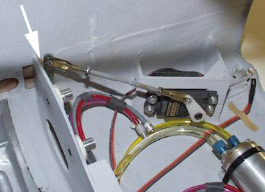
Note servo arm angle with flaps
full up. Clevis is in 1st hole of JR heavy duty servo arm and the 2nd hole on
the metal flap horn. Do not neglect the wood shim, flaps up stop
(arrow).
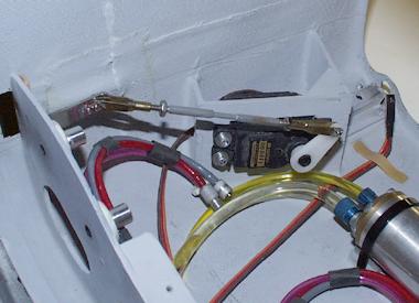
Note angle of the servo arm in the
flaps down position.
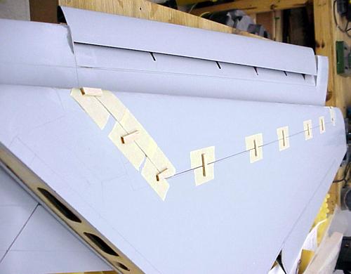
Installing the Slats
Steven Ellzey is a super precise
craftsman as well as being an Aerospace engineer, so I am sure F-100 builders
can benefit from his slat technique.
Steven says:
I finished up getting the
slats on the Hun, and they turned out working very smoothly (if you pick the
wing up leading edge down they will fall on the floor). I thought I would pass
on what I did, should it be of any help.
For fitting and gluing, a
layer of masking tape was applied to each side of the rails where they go into
the wing. This forced the rail to the center of the slot. The opening into the
spar on the slat was made a bit over sized, and the top of the rail, where it
meets the slat, was cut back a bit extra (1/64"). This was done so that when
the slat was held in place it would not touch, and possibly bend, the rails.
The slat was held in place by several pieces of balsa, CA'ed to masking tape
(see attached photos). This made sure that the OML (outer most layer) of the
slat matched the OML of the wing on the top. I also applied a thin layer of CA
to the edges of the rails where they go into the wing and polished it with 600
grit. I did this after the fact on one side and it seemed to help a bit when
the slat was loaded vertically. On the other side, I CA'ed and polished before I
glued them in (much easier). Other than the CA and polishing on the first side,
no work was done on the rails after being glued in.
 |
 |
The only problem I see so far is that the
slats are a bit thinner than the wing. Since I made the upper surface match as
is, I will putty the lower surface to match the lower OML of the wing, which
should be fairly easy to do. So far this looks like a very slick piece of
machinery.
Steven Ellzey
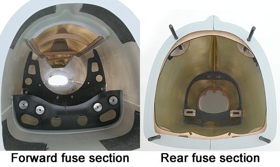
Inlet / Fuse Joint
The forward inlet/fuse joint can
be strengthened to reduce distortion during high power static and low
air speed run-ups and to prevent damage while handling the model. This
can be accomplished during construction or on a completed model.
Once the
forward inlet duct section has been glued in according to the
instructions, position the fuse nose down onto a flat surface (cover
with wax paper) and pour a mixture of resin and micro-balloons through
the openings of F-1.
Use one
and one half ounces of Pacer Finishing Resin mixed with micro-balloons
to form a thickened, but still pourable slurry.
Allow to cure with fuse in vertical position.
F-100 Stabilator Control Horns
some were tapped 4-40 vs 5-40
Our vendor for this part misread
the print and we did not catch the mistake prior to shipping some of
these units.
Check
that the part in your kit is properly setup for the #5-40 bolts that
mount the pushrods. If it is not, return it for a replacement. If you
have a #38 drill and 5-40 tap, you can correct the part in your shop.
Sorry for
the inconvenience.
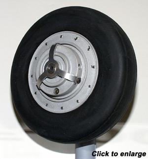
F-100 Wheel Brakes Retention
Note that the wheel brake hub is
retained to the axle with (2) "dog end" set screws that seat into a hole
through the wheel axle and are locked in place with secondary set
screws.
After
several flights you can check the security of these screws with a 5/64"
hex wrench.
We
have observed that after about 80 flights on our "D" model, the "dog
end" set screw is slightly bent but still functional.
Spare set screw sets are available - a nice
addition to your spare parts kit. Add it to your next order and save on
the postage.
Package #5828 contains:
(4) dog end 8-32 x 3/8"
(4) set
screw 8-32 x 1/4"
Price:
$4.00
F-100 Slat Servos
JR has
discontinued the 3321 servo that we call for in the instructions for use on the
slats.
The
replacement digital variety #3301 are temporarily out of stock. The Airtronics
94141 (metal gear) makes an excellent substitute. Two standard and two reverse
units are required. These servos allow manual operation of the slats. We always
like to see the slats extended for static display. See your Airtronics dealer.
F.T.E. has these units in stock - call 561-795-6600.
BV's new F-100F utilizes
the 94141's on the slats.
F-100 Speed Brake / Wheel Brakes mix on the JR
10X
We mixed the speed brake to the wheel brakes and assigned the
control to the Aux 3 channel.
The first 90% of side lever travel provides proportional braking for
taxi control. The last 10% activates the speed brake air valve servo control
servo.
I prefer
to fly the final approach with the speed brake deployed so that the glide slope
and touchdown point is very precisely controlled with power. Touching down with
the brakes "on" will yield a short roll out of about 200ft. If this is not
desired, move the Aux 3 lever just a bit prior to touchdown to release the
"full on" brakes and hold the nose high for a full flare landing.
For Futaba 9ZAP users
there is a device called the electronic switch that will help free up a
channel. BVM rep Paul Bageman has some experience with this item.
Landing Heavy
and Fail Safe setup
I had one occasion at Jets over Deland (Jan
'01) where the radio was indicating fail safe conditions shortly after
take-off.
I always
set the fail safe as follows:
Engine to idle, gear down, and a slight amount of up
stab.
The
"Hun" was on the downwind leg when I saw the gear extend, so I immediately
entered the landing pattern, dirtied up and set the power appropriately for a
heavy landing.
With about 90% of the 4.8 Liters of fuel remaining the slatted wing
handled the extra 5-6 pounds of fuel (above a normal landing) very well - just
keep the power on.
This experience confirms that we can add a few extra pounds worth of
missiles and bombs and enjoy the ultimate airborne appearance. Plenty of
reliable power is all that is needed.
Stab Servos - shim
To keep the servo cases from interfering with
the bottom fuse skin, it is necessary to add 1/8" ply shims to the inboard
faces of the stab servo mounts. BV's model has the bottom of the servo cases
protruding very slightly to keep a close check on servo temps after flight. So
far no problems, holes in the bottom of the fuse are not
necessary.
Stab Control Yoke
A very few parts may have been shipped out
with 4-40 threaded holes vs. the correct 5-40 threads. Contact BVM if you
received a 4-40 set.
3-View Drawings
We used the drawings from the War Paint Series
#4 booklet. 11" x 17" copies of the top, side and front view of the F-100D are
available from BVM.
Contact Us
All graphics, photos, and text
Copyright 2018 BVM, Inc.
Use of graphics or photos without written permission from
BVM is
strictly prohibited.
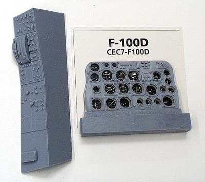
|
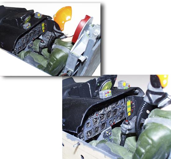
 F-100
customers have been very pleased with what you see here. It is technically
accurate and very detailed. The casting resin system is the best we have seen.
The parts are not warped and are reasonably light in weight. The instruction
package shows step-by-step assembly and painting, even including the correct
F.S. (Federal Standard) numbers.
F-100
customers have been very pleased with what you see here. It is technically
accurate and very detailed. The casting resin system is the best we have seen.
The parts are not warped and are reasonably light in weight. The instruction
package shows step-by-step assembly and painting, even including the correct
F.S. (Federal Standard) numbers.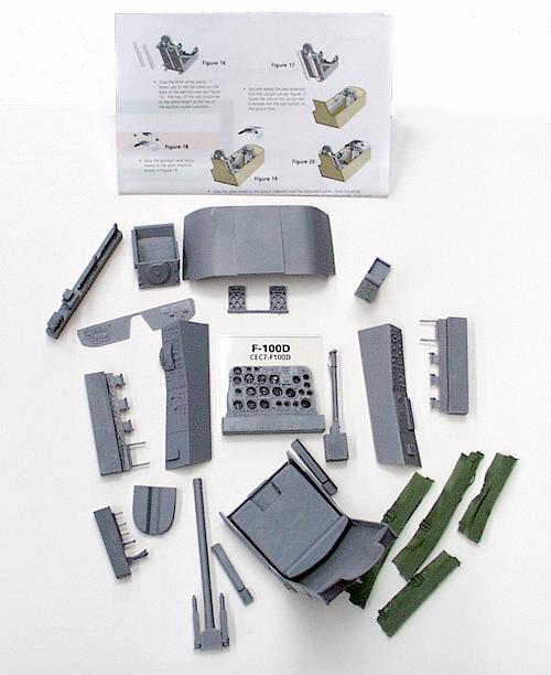


 Each leading edge slat rail has
been custom fitted at the factory into the precision machined tracks that are
built into the wings.
Each leading edge slat rail has
been custom fitted at the factory into the precision machined tracks that are
built into the wings.